Creality Ender-3 S1 simple Tool changer
Suggested price: €3.00
Summary
IMPORTANT NOTICE: Several people reached out to me with the problem that this doesn’t fit on their printer. It looks like the dimensions of the sheet metal part on which the extruder (so also this design) is mounted to, differs between printers. This can probably be solved by scaling the part horizontally (so the dimensions of the dovetail connection don’t change). This could require some trial and error and fortunately this is a quick print.
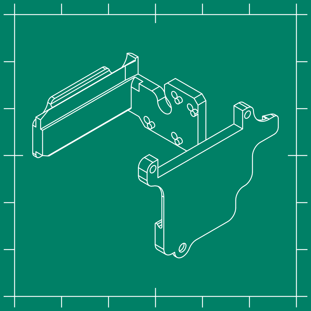
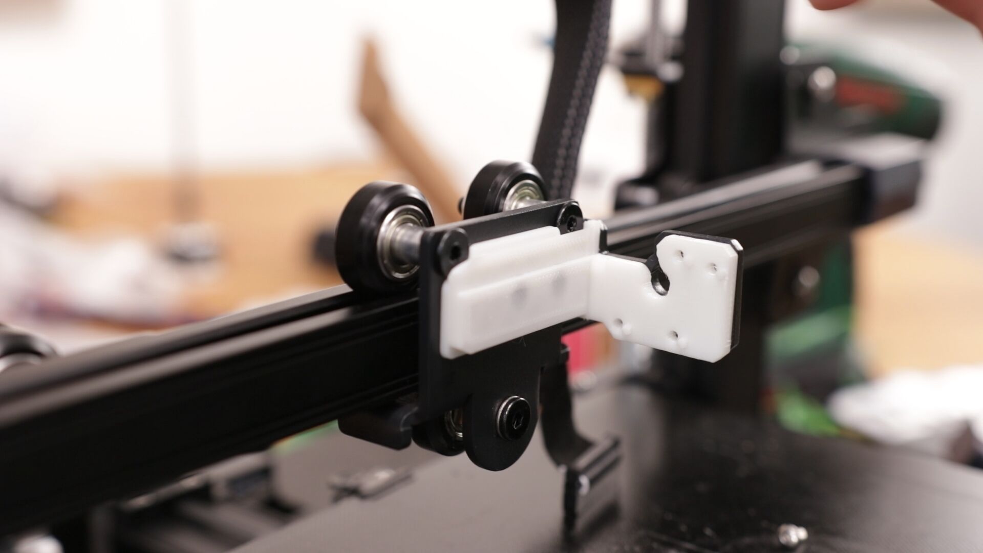
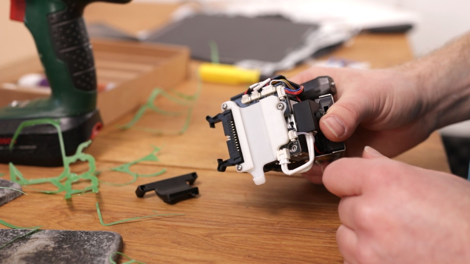
This is by far the simplest mod I ever made and it can be replicated with only the parts out of the Ender-3 S1’s box. It consists out of two 3D printed parts which can be printed out of regular PLA and take approximately 1.5 hours to print. It can be mounted with the screws used to mount the extruder and it doesn’t require inserts or nuts. What I didn’t show in the video was that the little notches which fall in the screw holes of the extruder itself need to be cut to size like in the picture below.
I also added a bit of lubricant to make it slide better.
The video I made of this modification:
PROPER PRINTING PROVIDES THE SOFTWARE AND DESIGNS TO YOU “AS IS” AND WITHOUT WARRANTY OF ANY KIND, EXPRESS, STATUTORY, IMPLIED OR OTHERWISE, INCLUDING WITHOUT LIMITATION ANY WARRANTY OF MERCHANTABILITY, FITNESS FOR A PARTICULAR PURPOSE OR INFRINGEMENT. NO ORAL OR WRITTEN INFORMATION OR ADVICE GIVEN TO YOU BY ANY PROPER PRINTING EMPLOYEE, REPRESENTATIVE OR DISTRIBUTOR WILL CREATE A WARRANTY FOR THE SOFTWARE, AND YOU MAY NOT RELY ON ANY SUCH INFORMATION OR ADVICE.
On a less formal note: Don’t hold me responsible when you destroy your printer or set your house on fire.
Print settings
Printer: Standard printer
Rafts: No
Supports: Yes
Resolution: 0.2
Infill: 30%
Filament: Standard PLA
Notes:
I used PLA to show that it’s possible to do the mod with only the parts out of the box. Other (stronger) materials might be better, but aren’t required. The right print orientation is as shown in this picture:
Parts needed
- -1 screw
Mounting instructions
- Make sure that both parts are printed correctly
- Disconnect the cable from the extruder assembly
- Remove all screws on the right side of the extruder assembly
- Remove the extruder assembly (this might require a bit of extra force due to the hot glue of the small connectors at the back)
- Press the base plate over the two standoffs
- Screw in the same screws on the right side and the screws create their own thread in the part.
- Remove the two screws which hold the strain relief of the cable and the longer screw that holds the circuit board of the extruder assembly
- Mount the Tool holder with those screws
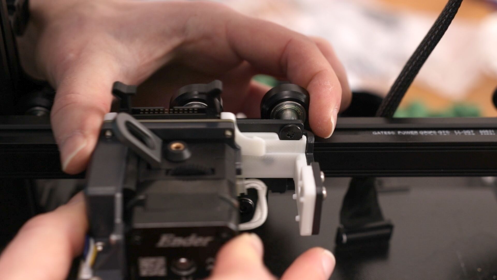
- Add a bit of lubricant to make it slide better
- If the assembly doesn’t slide all the way to the right, the notches need to be modified a bit.
Because it uses an automated bel leveling sensor, you can just continue on printing the next part!
Other tools
As I’ve shown in the video you can add your own custom hardware to it. I haven’t done that myself yet, but I reverse engineered the connector which can be used to create your own hardware. Bear in mind that the connector has a 2mm pitch so if you’re going to use a prototyping board, buy one with this pitch. This is less common. This is the pinout of the connector:
I started making a board in Eagle, but I haven’t finished it. If you need more information, or if something is not correct, don’t hesitate to contact me!
You must be logged in to post a review.


Reviews
There are no reviews yet.