The download contains the 3D printable (stl) files only. The Fusion 360 and/or STEP files are accesible to my Patreon supporters. Consider becoming a supporter yourself and get access to these files!
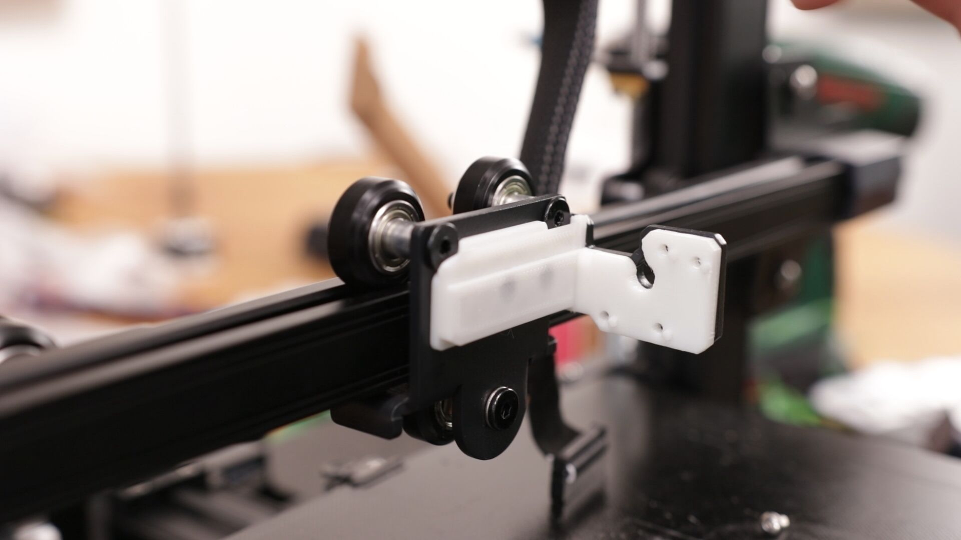
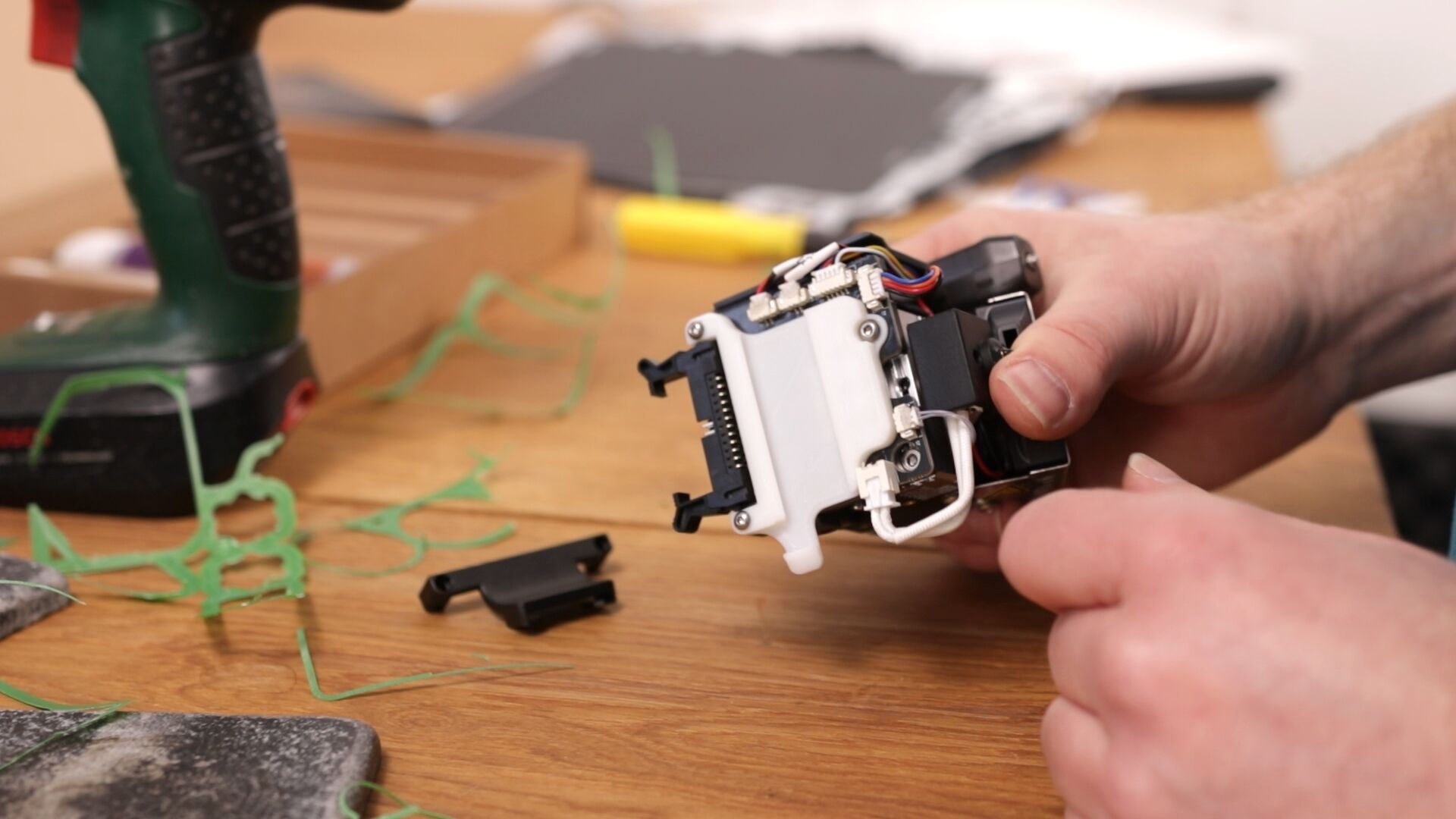
This is by far the simplest mod I ever made and it can be replicated with only the parts out of the Ender-3 S1’s box. It consists out of two 3D printed parts which can be printed out of regular PLA and take approximately 1.5 hours to print. It can be mounted with the screws used to mount the extruder and it doesn’t require inserts or nuts. What I didn’t show in the video was that the little notches which fall in the screw holes of the extruder itself need to be cut to size like in the picture below.
I also added a bit of lubricant to make it slide better.
The video I made of this modification:
PROPER PRINTING PROVIDES THE SOFTWARE AND DESIGNS TO YOU “AS IS” AND WITHOUT WARRANTY OF ANY KIND, EXPRESS, STATUTORY, IMPLIED OR OTHERWISE, INCLUDING WITHOUT LIMITATION ANY WARRANTY OF MERCHANTABILITY, FITNESS FOR A PARTICULAR PURPOSE OR INFRINGEMENT. NO ORAL OR WRITTEN INFORMATION OR ADVICE GIVEN TO YOU BY ANY PROPER PRINTING EMPLOYEE, REPRESENTATIVE OR DISTRIBUTOR WILL CREATE A WARRANTY FOR THE SOFTWARE, AND YOU MAY NOT RELY ON ANY SUCH INFORMATION OR ADVICE.
On a less formal note: Don’t hold me responsible when you destroy your printer or set your house on fire.
Print settings
Printer: Standard printer Rafts: No Supports: Yes Resolution: 0.2 Infill: 30% Filament: Standard PLA
Notes:
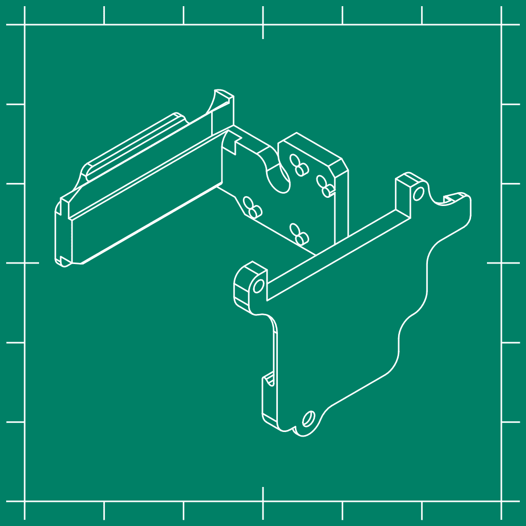
I used PLA to show that it’s possible to do the mod with only the parts out of the box. Other (stronger) materials might be better, but aren’t required. The right print orientation is as shown in this picture:
Parts needed
-1 screw
Mounting instructions
Make sure that both parts are printed correctly
Disconnect the cable from the extruder assembly
Remove all screws on the right side of the extruder assembly
Remove the extruder assembly (this might require a bit of extra force due to the hot glue of the small connectors at the back)
Press the base plate over the two standoffs
Screw in the same screws on the right side and the screws create their own thread in the part.
Remove the two screws which hold the strain relief of the cable and the longer screw that holds the circuit board of the extruder assembly
Mount the Tool holder with those screws
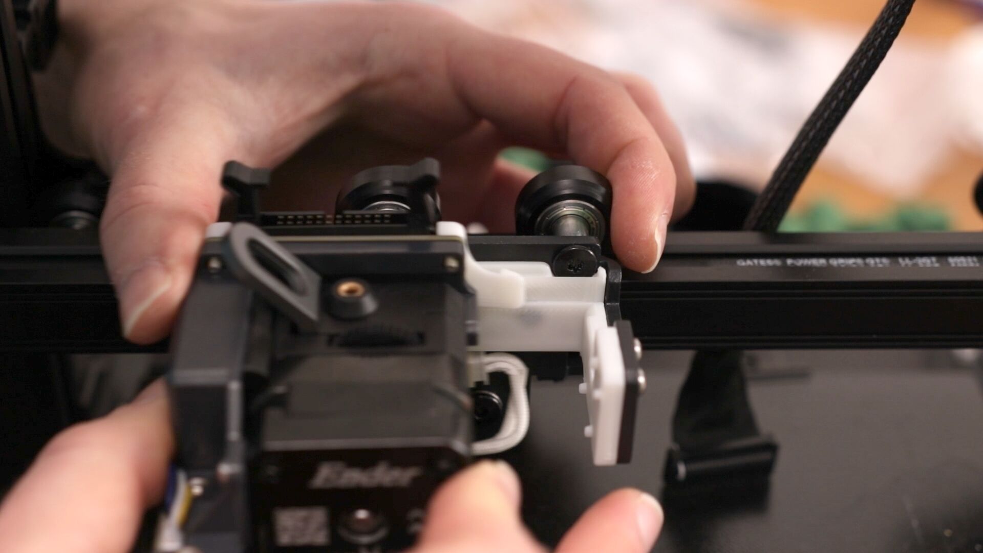
Add a bit of lubricant to make it slide better
If the assembly doesn’t slide all the way to the right, the notches need to be modified a bit.
Because it uses an automated bel leveling sensor, you can just continue on printing the next part!
Other tools
As I’ve shown in the video you can add your own custom hardware to it. I haven’t done that myself yet, but I reverse engineered the connector which can be used to create your own hardware. Bear in mind that the connector has a 2mm pitch so if you’re going to use a prototyping board, buy one with this pitch. This is less common. This is the pinout of the connector:
I started making a board in Eagle, but I haven’t finished it. If you need more information, or if something is not correct, don’t hesitate to contact me!
20 reviews for Creality Ender-3 S1 simple Tool changer
Rated 1 out of 5
juan (verified owner)–
i tried to print your holder 3 times with the setting you have and sliced it with cura and prusa and they come out junk!!!!
Jón –
Hi Juan, Thanks for your feedback! This should be a straight forward print. Did you print them at the right orientation? I added an image with the right print orientation in the print settings tab. Hopefully this helps!
Rated 4 out of 5
Johnathan Oey (verified owner)–
I dont know what the issue was with the previous rater/poster, but this printed perfectly on my Ender 3 S1…I didn’t have to change any setting from what was recommended…Fits great and seems to hold great… I gave it 4 stars for now…After some use and testing ill come back and give an updated review and rating…but for now, im very impressed…
Rated 4 out of 5
Mark –
I’ve printed this so easy, brilliant idea, is there files for a pen or Lazer holder. Simple but brilliant.
Rated 5 out of 5
Alan Neubauer (verified owner)–
I have to agree with juan. I printed these and they came out poorly. THEN I read the information you provided regarding the proper printing method. WOW, the results are exceptional. I have NEVER used a 3D printer. My first print was the smiling cat for my granddaughter. It came out nearly perfect so I figured that I would use your BRILLIANT tool changing system. I downloaded the files and printed. I did this as an ABSOLUTE Noob (this is my second 3D print project). After the 3rd failed print, I correctly guessed that I was missing something. I visited your PRINT SETTINGS tab. Head Slap moment. I changed the print orientation and made the configuration (supports specifically) changes. Night and Day improvement. I finished the prints flawlessly and immediately installed the base and tool holder (after removing the little nubs you mentioned in your PRINT SETTINGS tab and using a small diamond file (150 grit) to soften the top edge of the tool where part of the print head bracket has to slide over). PERFECT FIT. IMPORTANT, if you are a Noob like me don’t forget to recalibrate (level) your machine. Once I adjusted the level and got all setting tuned for the new bracket assembly. This is a great, albeit simple, enhancement to my machine (Ender 3D S1 Pro). The ONLY Question I have is concerning the flexible ribbon cable. The original design had a supporting shelf to stabilize that critical connection point. I don’t think it will come apart due to the clipping mechanism, instead I am worried about how the cable will hold up over time with the constant flexing and bending while unsupported. Do you have a solution planned for that or is it something, in your opinion, that I shouldn’t have to worry about?
Jón –
Hi Alan. Thanks for your thorough feedback and I’m happy that you eventually got it working! I often forget to orient it correctly from my design software and I’ve gotten used to orienting it in the slicer itself. Regarding the strain relieve: I haven’t added it to make the tool easier to swap, but in the long run it would be better. Since I’m only using it for servicing at the moment I folded the cable at the connector and added a zip-tie around the connector and cable. This way it’s more secure, but it cannot be released. Maybe it’s a good idea to add strain relieve, but that makes things more complicated. My advise would be to zip-tie it if you’re planning on doing longer prints ore aren’t swapping much.
Rated 5 out of 5
Éric Cardinal (verified owner)–
Hi Jón… Great work, I was looking for that exact solution to be able to switch between my 2 heads (using 0.8mm and 0.4mm).
The only problem I have, is that my back plate has round screws for the wheel (not flat like yours). This prevent the base print to sit flush on the back plate 🙁
Thanks , Éric
Rated 5 out of 5
Kenny Berglund (verified owner)–
With this, X and Y offsets needs a little change, have you given any thought your model would do this? Please add the correct offsets for it.
Thanks
Jón –
I personally didn’t run into issues with the offset this adds. The printer runs its ABL routine nicely and I can reach the full build volume. What exact issue do you run into?
Rated 5 out of 5
Timo –
Amazing job Jón! Thanks for sharing the idea and the files. I printed it on my EnderS1 and it worked well with the first try. I was wondering if you could also provide a holderplate for the Ender Laser-Head? Then it would be really awesome, to switch easily between Laser and Extruder 🙂
I’m giving 5 stars simply for the concept and the implementations I’ve seen, however, turns out it doesn’t work on the CR10 Smart Pro, I think this is due to a mixture of a slightly different mounting bracket that is shorter than that on the ender 3 s1, and may also be in part due to the fact the this printer uses the Pro’s hotend, I’m making my own custom rudimentary modifications to the mesh model to see if I can get it to fit and function on this printer but not sure at the moment.
Rated 5 out of 5
Kai Gunter Brandt –
I have two Ender 3 S1 and this tool changer is saving a lot of time.
Now i can easily swap between the laser engraver, extruder 1 with 0.4 nozzle, extruder 2 with 0.8 nozzle and the all metal sprite extruder.
Got inspired by Jón’s pen adapter using a solenoid. So i’ll try to make my own design but use this tool changer.
Rated 5 out of 5
Anon Q –
Hi could make a version for the kit of the sprite pro extruder and what are the offsets the plate on which the wheels are which comes with the kit has a hole where one of the stand offs should be .
Rated 4 out of 5
Andrzej Róg (verified owner)–
Prints easily and working really great(as expected). I’m only missing cable holder (longer screws, or can you suggest smth else?).
I was also wondering looking for pi out… But it’s to complicated. Would be great to have place buck converters under printer and use original cable to provide 12-24v as needed.
Rated 3 out of 5
Rene (verified owner)–
Despite perfect print (measured with caliper tool), it needs some adjustments around the nobs for the extruder to slide the last stretch to the right. Would be great to have a revised model here.
More annoyingly, my extruder hit the left limit when homing, as the bracket adds 4mm X offset.. would be nice to have that in the description on how to fix on Ender S1. Many thanks
Rated 2 out of 5
Cameron (verified owner)–
I think this design is ingenious so I really wanted this to work; however I ran into issues; I have the S1 Pro, so maybe that is the issue; but after tightening the 4 screws on the right side to the PLA mount plate, the back of mount does not stay flush against the back of the stock metal bracket mount, and there are no screws there to be secured against; this makes it so the entire print head is slightly wobbly as it can pull away from the back of the mount. The head did not feel secure; it seemed like the tolerances were slightly off; which could be the reason it really wasn’t sitting fully tight and flush due to some slight difference of the S1 Pro vs. S1 model; As the head was not fully secured, I ended up removing this mod; as a floppy nozzle would not be good for prints.
It also has no ribbon strain relief after installing… so I figure I’d be better off with the stock configuration; 4 screws are really not that hard to remove; although I would have liked quick release much better. Would like to see some redesign to really hold it securely.
Rated 5 out of 5
Juergen (verified owner)–
I must say, that is the best idea I ever seen. It is sitting perfekt and taking up the extruder is now very simpel. Thank you so much for it. Many greating from Germany.
Rated 5 out of 5
John D (verified owner)–
This is awesome have just fitted it to my new Ender 3 s1 pro straight out of its box and then fitted the bracket to the cv-laser module, it all works great, AWESOME MOD.
Rated 3 out of 5
diego (verified owner)–
i have same problem like Cameron (verified owner) – August 30, 2022
I think this design is ingenious so I really wanted this to work; however I ran into issues; I have the S1 Pro, so maybe that is the issue; but after tightening the 4 screws on the right side to the PLA mount plate, the back of mount does not stay flush against the back of the stock metal bracket mount, and there are no screws there to be secured against; this makes it so the entire print head is slightly wobbly as it can pull away from the back of the mount. The head did not feel secure; it seemed like the tolerances were slightly off; which could be the reason it really wasn’t sitting fully tight and flush due to some slight difference of the S1 Pro vs. S1 model; As the head was not fully secured, I ended up removing this mod; as a floppy nozzle would not be good for prints.
It also has no ribbon strain relief after installing… so I figure I’d be better off with the stock configuration; 4 screws are really not that hard to remove; although I would have liked quick release much better. Would like to see some redesign to really hold it securely.
Rated 4 out of 5
Kimiko (verified owner)–
Very close. I printed this 4 times with supports and couldn’t figure out why the BL/CR touch kept drooping lower than the nozzle and knocking prints off the bed… I eventually removed it while it was still hot and found that the PLA I used was warping, leaning the nozzle to the left 🙁
While this is more the fault of the PLA than the design, I wanted this to work so badly. Taking the extruder off for nozzle changes was great but the eventual leaning/warping means I had to reinstall the original mounts.
The other minor issue was that the “clip” on the right, never engaged fully.
Mahalo for being so innovative. I will keep checking your YouTube for other prints.
Have a wonderful day!
Rated 1 out of 5
Randall (verified owner)–
Save your money. I cannot print with it attached. It’s not firmly attached on the back of the gantry piece and it droops down and the nozzle is a few mm above the fan and probe.
Rated 3 out of 5
Ferenc (verified owner)–
Both parts printed fine and works as intended. But… after I installed it I found not much use of it. Okay, I can quickly remove the original hotend from my printer but cannot install anything else on its place as I do not have the drawing of the sliding part. So I cannot make another part for my laser head, other hotend (for e.g. E3D) or anything for my need. I could hack from the STL but… may I have a drawing of the slide outline shape please? (the one on the hotend side, not the one on the printer carriage) That way we could make a nice collection of adapters and could make this idea even better.
Rated 5 out of 5
Paul Aviles (verified owner)–
What an amazing idea, I had no issues with printing the parts and used PLA+ with 100% infill. Not even had to add support and the L shaped part has the longer part vertically, basically with the part that holds the screw towards the bed. Just printed two sets and ordered another Sprite Pro, one for regular prints and one for Fiber Carbon so two different heads.
juan (verified owner) –
i tried to print your holder 3 times with the setting you have and sliced it with cura and prusa and they come out junk!!!!
Jón –
Hi Juan, Thanks for your feedback! This should be a straight forward print. Did you print them at the right orientation? I added an image with the right print orientation in the print settings tab. Hopefully this helps!
Johnathan Oey (verified owner) –
I dont know what the issue was with the previous rater/poster, but this printed perfectly on my Ender 3 S1…I didn’t have to change any setting from what was recommended…Fits great and seems to hold great… I gave it 4 stars for now…After some use and testing ill come back and give an updated review and rating…but for now, im very impressed…
Mark –
I’ve printed this so easy, brilliant idea, is there files for a pen or Lazer holder. Simple but brilliant.
Alan Neubauer (verified owner) –
I have to agree with juan. I printed these and they came out poorly. THEN I read the information you provided regarding the proper printing method. WOW, the results are exceptional. I have NEVER used a 3D printer. My first print was the smiling cat for my granddaughter. It came out nearly perfect so I figured that I would use your BRILLIANT tool changing system. I downloaded the files and printed. I did this as an ABSOLUTE Noob (this is my second 3D print project). After the 3rd failed print, I correctly guessed that I was missing something. I visited your PRINT SETTINGS tab. Head Slap moment. I changed the print orientation and made the configuration (supports specifically) changes. Night and Day improvement. I finished the prints flawlessly and immediately installed the base and tool holder (after removing the little nubs you mentioned in your PRINT SETTINGS tab and using a small diamond file (150 grit) to soften the top edge of the tool where part of the print head bracket has to slide over). PERFECT FIT. IMPORTANT, if you are a Noob like me don’t forget to recalibrate (level) your machine. Once I adjusted the level and got all setting tuned for the new bracket assembly. This is a great, albeit simple, enhancement to my machine (Ender 3D S1 Pro). The ONLY Question I have is concerning the flexible ribbon cable. The original design had a supporting shelf to stabilize that critical connection point. I don’t think it will come apart due to the clipping mechanism, instead I am worried about how the cable will hold up over time with the constant flexing and bending while unsupported. Do you have a solution planned for that or is it something, in your opinion, that I shouldn’t have to worry about?
Jón –
Hi Alan. Thanks for your thorough feedback and I’m happy that you eventually got it working! I often forget to orient it correctly from my design software and I’ve gotten used to orienting it in the slicer itself. Regarding the strain relieve: I haven’t added it to make the tool easier to swap, but in the long run it would be better. Since I’m only using it for servicing at the moment I folded the cable at the connector and added a zip-tie around the connector and cable. This way it’s more secure, but it cannot be released. Maybe it’s a good idea to add strain relieve, but that makes things more complicated. My advise would be to zip-tie it if you’re planning on doing longer prints ore aren’t swapping much.
Éric Cardinal (verified owner) –
Hi Jón… Great work, I was looking for that exact solution to be able to switch between my 2 heads (using 0.8mm and 0.4mm).
The only problem I have, is that my back plate has round screws for the wheel (not flat like yours). This prevent the base print to sit flush on the back plate 🙁
Thanks , Éric
Kenny Berglund (verified owner) –
With this, X and Y offsets needs a little change, have you given any thought your model would do this? Please add the correct offsets for it.
Thanks
Jón –
I personally didn’t run into issues with the offset this adds. The printer runs its ABL routine nicely and I can reach the full build volume. What exact issue do you run into?
Timo –
Amazing job Jón! Thanks for sharing the idea and the files. I printed it on my EnderS1 and it worked well with the first try. I was wondering if you could also provide a holderplate for the Ender Laser-Head? Then it would be really awesome, to switch easily between Laser and Extruder 🙂
Jón –
Thanks for using my design and I’m glad it worked well! Someone on Printables made a holder for a laser engraver https://www.printables.com/model/192454-cv-laser-module-holder-for-ender-3-s1 Maybe this fits yours too.
Yzin Khader (verified owner) –
I’m giving 5 stars simply for the concept and the implementations I’ve seen, however, turns out it doesn’t work on the CR10 Smart Pro, I think this is due to a mixture of a slightly different mounting bracket that is shorter than that on the ender 3 s1, and may also be in part due to the fact the this printer uses the Pro’s hotend, I’m making my own custom rudimentary modifications to the mesh model to see if I can get it to fit and function on this printer but not sure at the moment.
Kai Gunter Brandt –
I have two Ender 3 S1 and this tool changer is saving a lot of time.
I made a quick not perfect but workable adaption for my CV laser engraver:
https://www.printables.com/model/192454-cv-laser-module-holder-for-ender-3-s1
Now i can easily swap between the laser engraver, extruder 1 with 0.4 nozzle, extruder 2 with 0.8 nozzle and the all metal sprite extruder.
Got inspired by Jón’s pen adapter using a solenoid. So i’ll try to make my own design but use this tool changer.
Anon Q –
Hi could make a version for the kit of the sprite pro extruder and what are the offsets the plate on which the wheels are which comes with the kit has a hole where one of the stand offs should be .
Andrzej Róg (verified owner) –
Prints easily and working really great(as expected). I’m only missing cable holder (longer screws, or can you suggest smth else?).
I was also wondering looking for pi out… But it’s to complicated. Would be great to have place buck converters under printer and use original cable to provide 12-24v as needed.
Rene (verified owner) –
Despite perfect print (measured with caliper tool), it needs some adjustments around the nobs for the extruder to slide the last stretch to the right. Would be great to have a revised model here.
More annoyingly, my extruder hit the left limit when homing, as the bracket adds 4mm X offset.. would be nice to have that in the description on how to fix on Ender S1. Many thanks
Cameron (verified owner) –
I think this design is ingenious so I really wanted this to work; however I ran into issues; I have the S1 Pro, so maybe that is the issue; but after tightening the 4 screws on the right side to the PLA mount plate, the back of mount does not stay flush against the back of the stock metal bracket mount, and there are no screws there to be secured against; this makes it so the entire print head is slightly wobbly as it can pull away from the back of the mount. The head did not feel secure; it seemed like the tolerances were slightly off; which could be the reason it really wasn’t sitting fully tight and flush due to some slight difference of the S1 Pro vs. S1 model; As the head was not fully secured, I ended up removing this mod; as a floppy nozzle would not be good for prints.
It also has no ribbon strain relief after installing… so I figure I’d be better off with the stock configuration; 4 screws are really not that hard to remove; although I would have liked quick release much better. Would like to see some redesign to really hold it securely.
Juergen (verified owner) –
I must say, that is the best idea I ever seen. It is sitting perfekt and taking up the extruder is now very simpel. Thank you so much for it. Many greating from Germany.
John D (verified owner) –
This is awesome have just fitted it to my new Ender 3 s1 pro straight out of its box and then fitted the bracket to the cv-laser module, it all works great, AWESOME MOD.
diego (verified owner) –
i have same problem like Cameron (verified owner) – August 30, 2022
I think this design is ingenious so I really wanted this to work; however I ran into issues; I have the S1 Pro, so maybe that is the issue; but after tightening the 4 screws on the right side to the PLA mount plate, the back of mount does not stay flush against the back of the stock metal bracket mount, and there are no screws there to be secured against; this makes it so the entire print head is slightly wobbly as it can pull away from the back of the mount. The head did not feel secure; it seemed like the tolerances were slightly off; which could be the reason it really wasn’t sitting fully tight and flush due to some slight difference of the S1 Pro vs. S1 model; As the head was not fully secured, I ended up removing this mod; as a floppy nozzle would not be good for prints.
It also has no ribbon strain relief after installing… so I figure I’d be better off with the stock configuration; 4 screws are really not that hard to remove; although I would have liked quick release much better. Would like to see some redesign to really hold it securely.
Kimiko (verified owner) –
Very close. I printed this 4 times with supports and couldn’t figure out why the BL/CR touch kept drooping lower than the nozzle and knocking prints off the bed… I eventually removed it while it was still hot and found that the PLA I used was warping, leaning the nozzle to the left 🙁
While this is more the fault of the PLA than the design, I wanted this to work so badly. Taking the extruder off for nozzle changes was great but the eventual leaning/warping means I had to reinstall the original mounts.
The other minor issue was that the “clip” on the right, never engaged fully.
Mahalo for being so innovative. I will keep checking your YouTube for other prints.
Have a wonderful day!
Randall (verified owner) –
Save your money. I cannot print with it attached. It’s not firmly attached on the back of the gantry piece and it droops down and the nozzle is a few mm above the fan and probe.
Ferenc (verified owner) –
Both parts printed fine and works as intended. But… after I installed it I found not much use of it. Okay, I can quickly remove the original hotend from my printer but cannot install anything else on its place as I do not have the drawing of the sliding part. So I cannot make another part for my laser head, other hotend (for e.g. E3D) or anything for my need. I could hack from the STL but… may I have a drawing of the slide outline shape please? (the one on the hotend side, not the one on the printer carriage) That way we could make a nice collection of adapters and could make this idea even better.
Paul Aviles (verified owner) –
What an amazing idea, I had no issues with printing the parts and used PLA+ with 100% infill. Not even had to add support and the L shaped part has the longer part vertically, basically with the part that holds the screw towards the bed. Just printed two sets and ordered another Sprite Pro, one for regular prints and one for Fiber Carbon so two different heads.
Again, thanks and pretty amazing!