The Truss gantry system
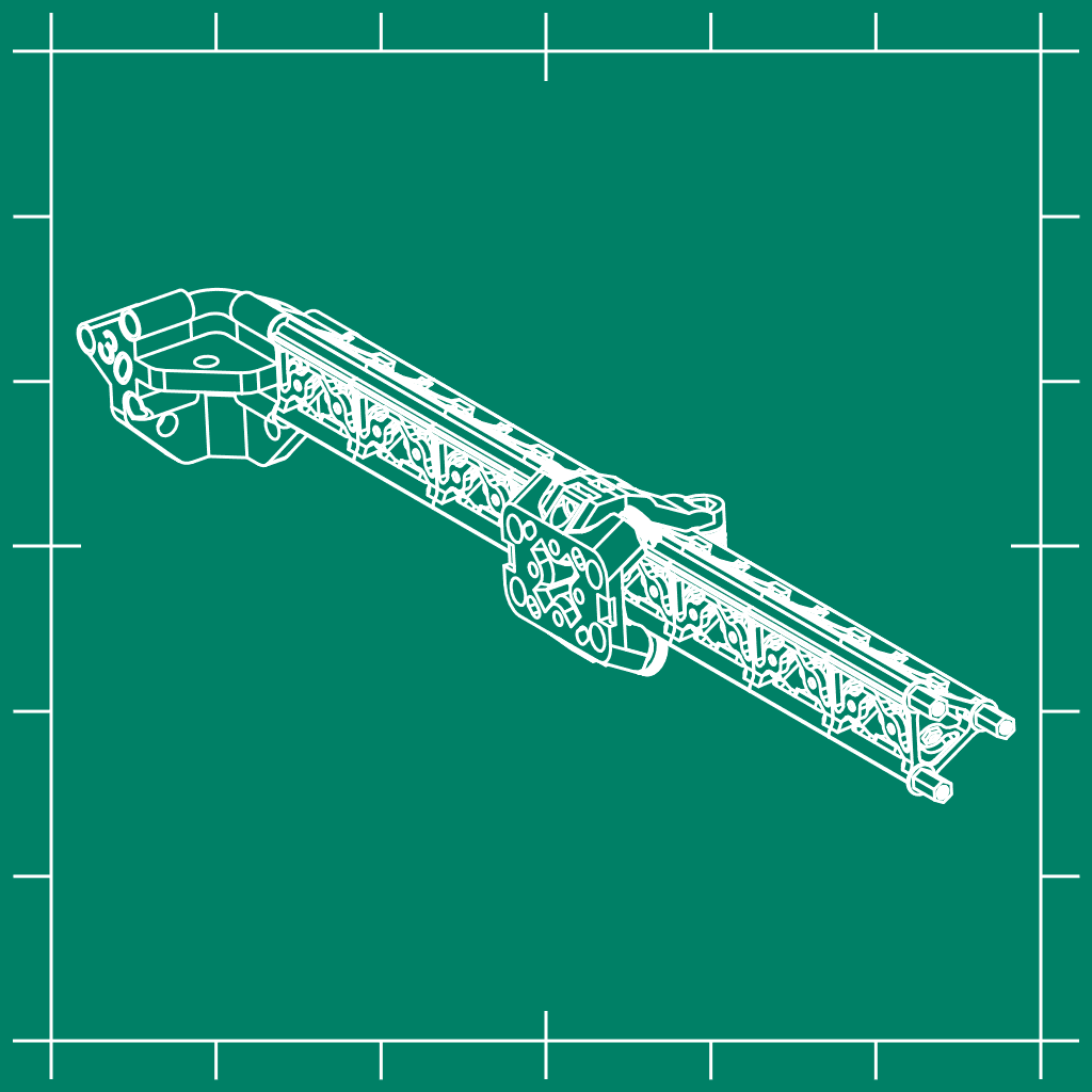
Experimental gantry system based of a truss.
Suggested price: €3.00
Summary
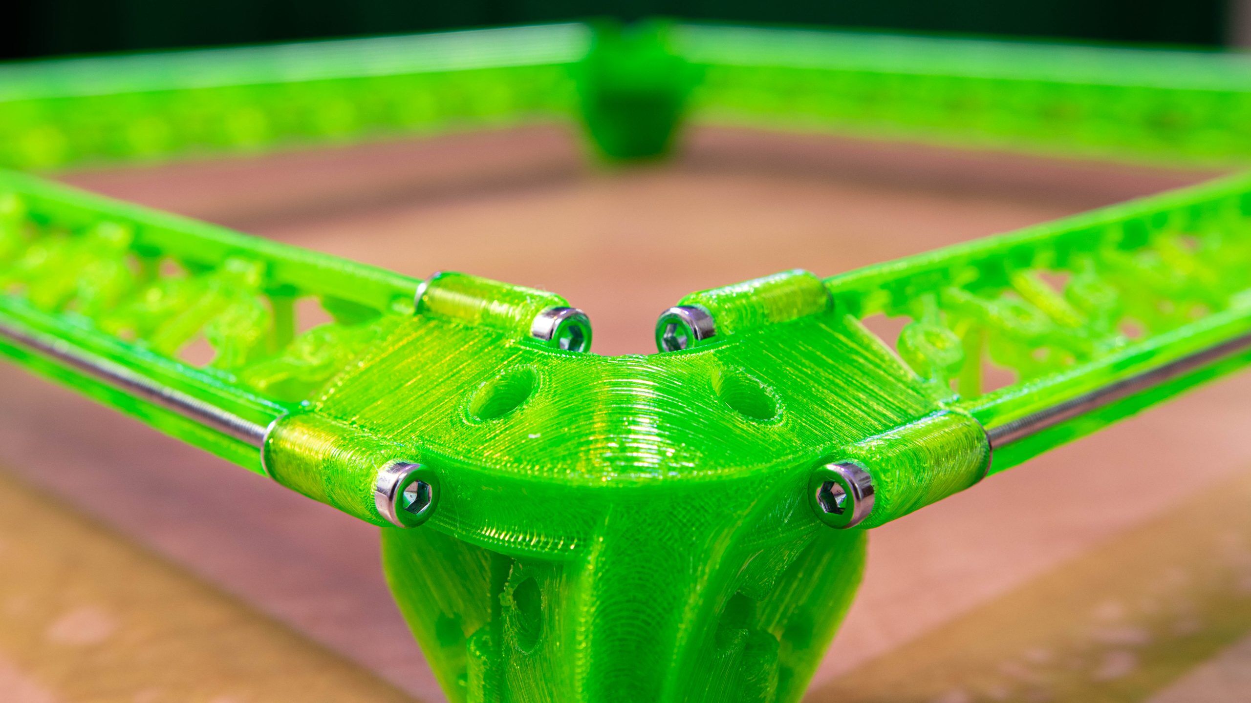
This is an experimental system that is based off the structure of a truss to make it light and stiff. This is an unusual shape, but can create interesting structures. The idea sparked after I came across skeletonized gantries which already look like trusses, but these are still square to make it a better drop-in replacement. A triangle shape is stiffer and lighter since there are only push and pull forces internally and no bending forces.
The design consists put of individual segments at a length of 30mm and they are held together using M3 threaded rods.
It’s important to note that this design needs to be optimized, meaning that it probably will undergo changes. This means that the parts needed can change as well!
I show the thought process behind this design and how it’s put together in this video:
Print settings
Printer: Sovol SV06 PLUS
Brim: Yes, especially with the corner pieces
Supports: Yes, only with the individual segments
Nozzle diameter: 0.4mm and the rollers are printed with 0.2mm
Layer height: 0.2mm
Infill: 30%
Filament: Fluor Green PLA from 3D4Makers
Notes:
The corner pieces can be printed without using support, but require good bed adhesion since the first layers have a very small surface. This requires a brim of at least 8 perimeters and possibly two layers. Due to the shape, this brim can be removed easily.
Parts needed
This is still in concept phase, so chances are that this design will undergo changes probably making the parts as mentioned below obsolete! Only buy the parts if you want to test it out or actually see a practical use case!
The parts you need to create one gantry (without carriage) with a length of 240mm is:
| QTY | Description | Link* |
| 8 | 30mm segment | |
| 3 | M3x250mm threaded rod | https://geni.us/BiE6364 |
| 6 | M3x8mm brass standoff | https://geni.us/s4jl2 |
| 6 | M3 washer | https://geni.us/pMQqz |
*Commissions are earned from the links above which help funding this project. If you have found a better alternative for a component, please let me know!
The gantries can be coupled together with the corner pieces (versions can be found in the corner pieces tab). These require 6 M3 x 10mm screws for each gantry https://geni.us/Xg6PYG
The parts you need for one carriage:
| QTY | Description | Link* |
| 1 | Carriage body | |
| 2 | Carriage holder | |
| 5 | Roller | |
| 5 | MR63ZZ ball bearing | https://geni.us/8t2M |
| 10 | 3mm seal washer | https://geni.us/wFjsikc |
| 7 | M3 nut | https://geni.us/BViqH |
| 6 | M3 x 15-20 mm screw | https://geni.us/2DTvfGn |
| 1 | M3 x 10 mm screw | https://geni.us/Xg6PYG |
Corner pieces
There are multiple corner pieces and a lot of variants are possible. To create the gantry as shown in the video I needed two variants. Each variant has its own part number that is built up based on the angles. I recommend only using one of the four versions in the download.
The list of variants are:
| Angle 1 | Angle 2 | Rot 1 | Rot 2 | Rot 3 | Version (L/R) | Part number | Designed | Verified |
| 90 | 90 | 30 | 30 | 45 | R | CP9090303045R | x | x |
| 90 | 90 | 30 | 30 | 45 | L | CP9090303045L | x | x |
| 90 | 90 | 30 | 30 | 105 | R | CP90903030105R | x | |
| 90 | 90 | 30 | 30 | 105 | L | CP90903030105L | x | |
| 90 | 90 | 60 | 60 | 45 | R | CP9090606045R | ||
| 90 | 90 | 60 | 60 | 45 | L | CP9090606045L | ||
| 90 | 90 | 60 | 60 | 105 | R | CP90906060105R | ||
| 90 | 90 | 60 | 60 | 105 | L | CP90906060105L | ||
| 90 | 90 | 0 | 0 | 45 | R | CP909045R | ||
| 90 | 90 | 0 | 0 | 45 | L | CP909045L | ||
| 90 | 90 | 0 | 0 | 105 | R | CP9090105R | ||
| 90 | 90 | 0 | 0 | 105 | L | CP9090105L | ||
| 90 | 90 | 30 | 30 | 30 | R | CP9090303030R | ||
| 90 | 90 | 30 | 30 | 30 | L | CP9090303030L | ||
| 90 | 90 | 30 | 30 | 60 | R | CP9090303060R | ||
| 90 | 90 | 30 | 30 | 60 | L | CP9090303060L | ||
| 90 | 90 | 60 | 60 | 30 | R | CP9090606030R | ||
| 90 | 90 | 60 | 60 | 30 | L | CP9090606030L | ||
| 90 | 90 | 60 | 60 | 60 | R | CP9090606060R | ||
| 90 | 90 | 60 | 60 | 60 | L | CP9090606060L | ||
| 90 | 90 | 0 | 0 | 30 | R | CP909030R | ||
| 90 | 90 | 0 | 0 | 30 | L | CP909030L | ||
| 90 | 90 | 0 | 0 | 60 | R | CP909060R | ||
| 90 | 90 | 0 | 0 | 60 | L | CP909060L | ||
| 120 | 90 | 30 | 30 | 45 | R | CP12090303045R | ||
| 120 | 90 | 30 | 30 | 45 | L | CP12090303045L | ||
| 120 | 90 | 30 | 30 | 105 | R | CP120903030105R | ||
| 120 | 90 | 30 | 30 | 105 | L | CP120903030105L | ||
| 120 | 90 | 60 | 60 | 45 | R | CP12090606045R | ||
| 120 | 90 | 60 | 60 | 45 | L | CP12090606045L | ||
| 120 | 90 | 60 | 60 | 105 | R | CP120906060105R | ||
| 120 | 90 | 60 | 60 | 105 | L | CP120906060105L | ||
| 120 | 90 | 0 | 0 | 45 | R | CP1209045R | ||
| 120 | 90 | 0 | 0 | 45 | L | CP1209045L | ||
| 120 | 90 | 0 | 0 | 105 | R | CP12090105R | ||
| 120 | 90 | 0 | 0 | 105 | L | CP12090105L | ||
| 120 | 90 | 30 | 30 | 30 | R | CP12090303030R | ||
| 120 | 90 | 30 | 30 | 30 | L | CP12090303030L | ||
| 120 | 90 | 30 | 30 | 60 | R | CP12090303060R | ||
| 120 | 90 | 30 | 30 | 60 | L | CP12090303060L | ||
| 120 | 90 | 60 | 60 | 30 | R | CP12090606030R | ||
| 120 | 90 | 60 | 60 | 30 | L | CP12090606030L | ||
| 120 | 90 | 60 | 60 | 60 | R | CP12090606060R | ||
| 120 | 90 | 60 | 60 | 60 | L | CP12090606060L | ||
| 120 | 90 | 0 | 0 | 30 | R | CP1209030R | ||
| 120 | 90 | 0 | 0 | 30 | L | CP1209030L | ||
| 120 | 90 | 0 | 0 | 60 | R | CP1209060R | ||
| 120 | 90 | 0 | 0 | 60 | L | CP1209060L |
Mounting instructions
I show most of the process in the video as shown in the first tab. Things to keep in mind building this are:
- The rods need to be 10mm longer than the stacked segments, so 8 segments of 30mm requires a rod length of 250mm. It’s important to not make it longer, otherwise the screw on the opposing end in the spacer will collide with the rod making it impossible to tighten it.
- The rods are exposed due to the carriage, this means that during tensioning it can pop out.
- The segments don’t slide on the rods, so after tensioning you can try and bend it a little to get it into shape better and tension it a bit more.
If you have suggestions on how to improve this design or if you have an interesting use case for it, let me know!
You must be logged in to post a review.


Reviews
There are no reviews yet.