Ender 3 dual Z axis with optional frame braces
Suggested price: €3.00
Summary
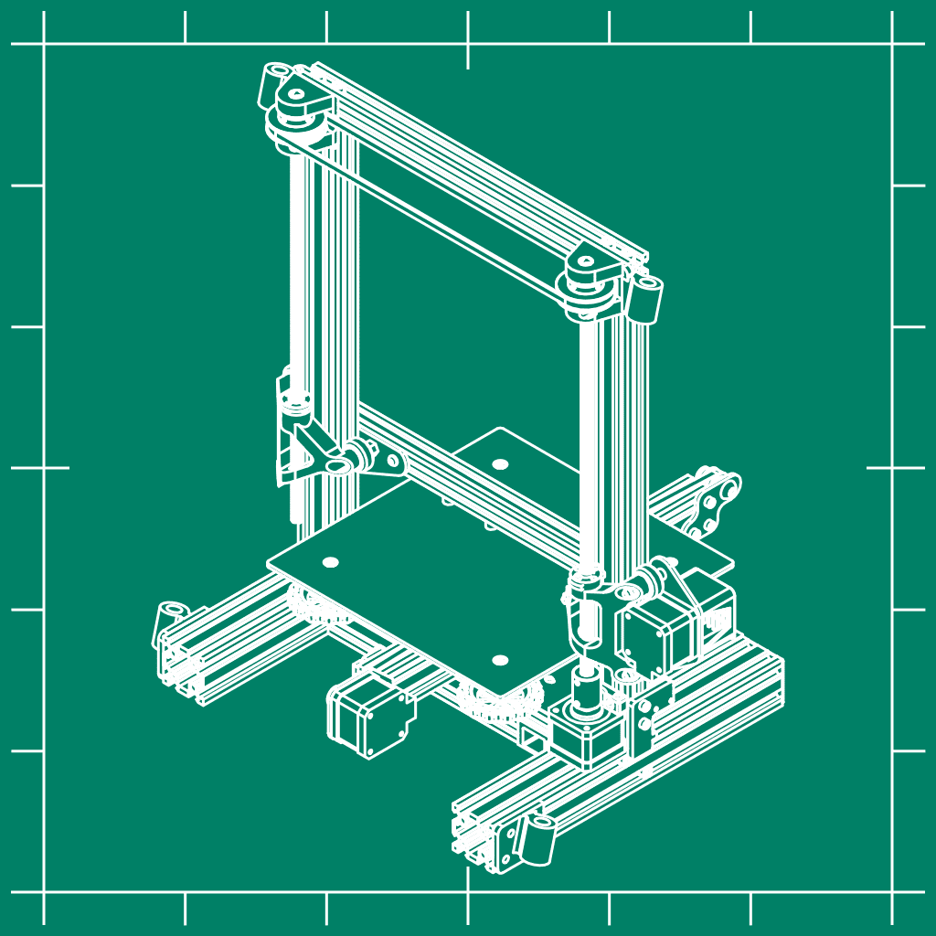
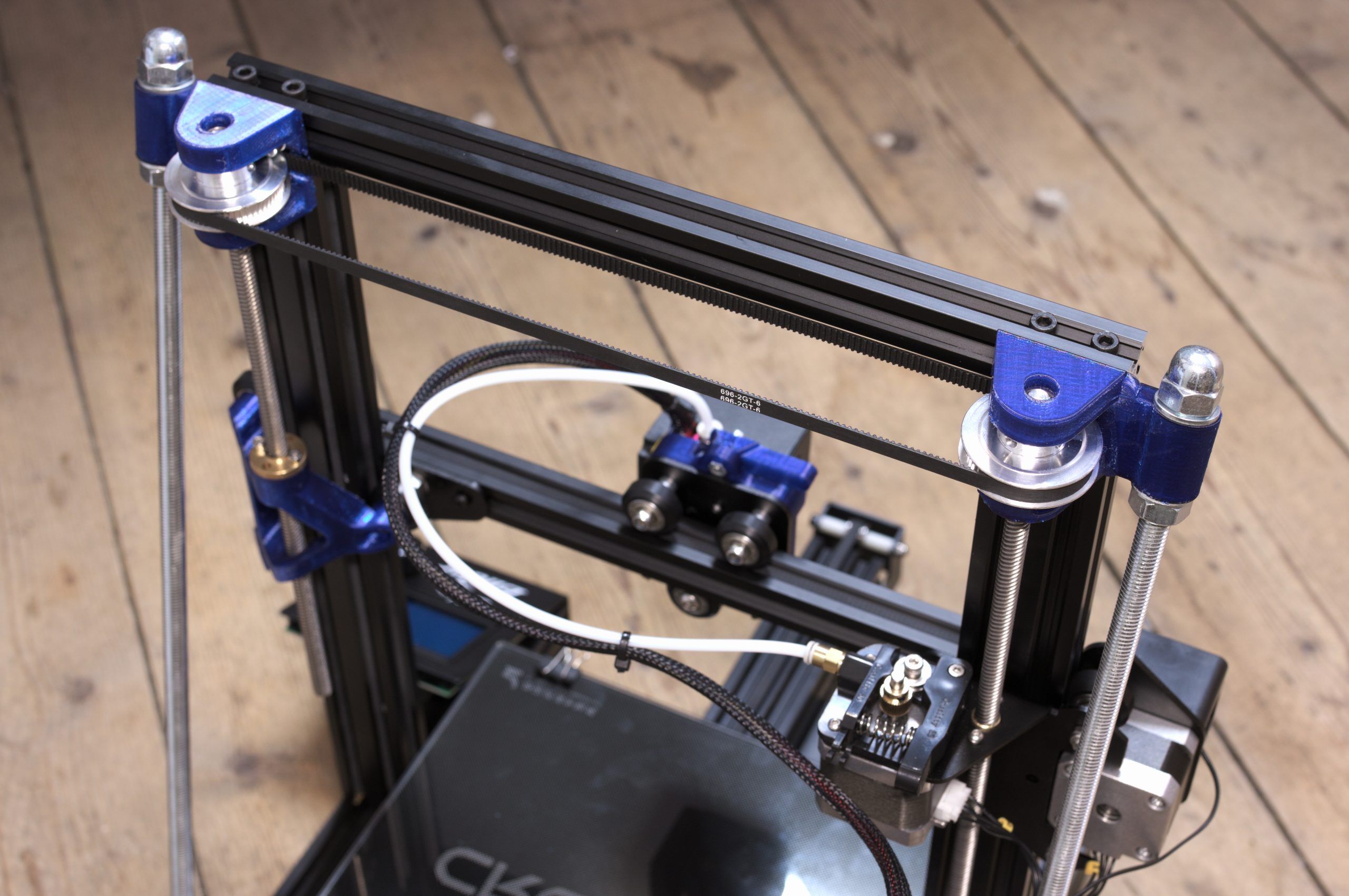
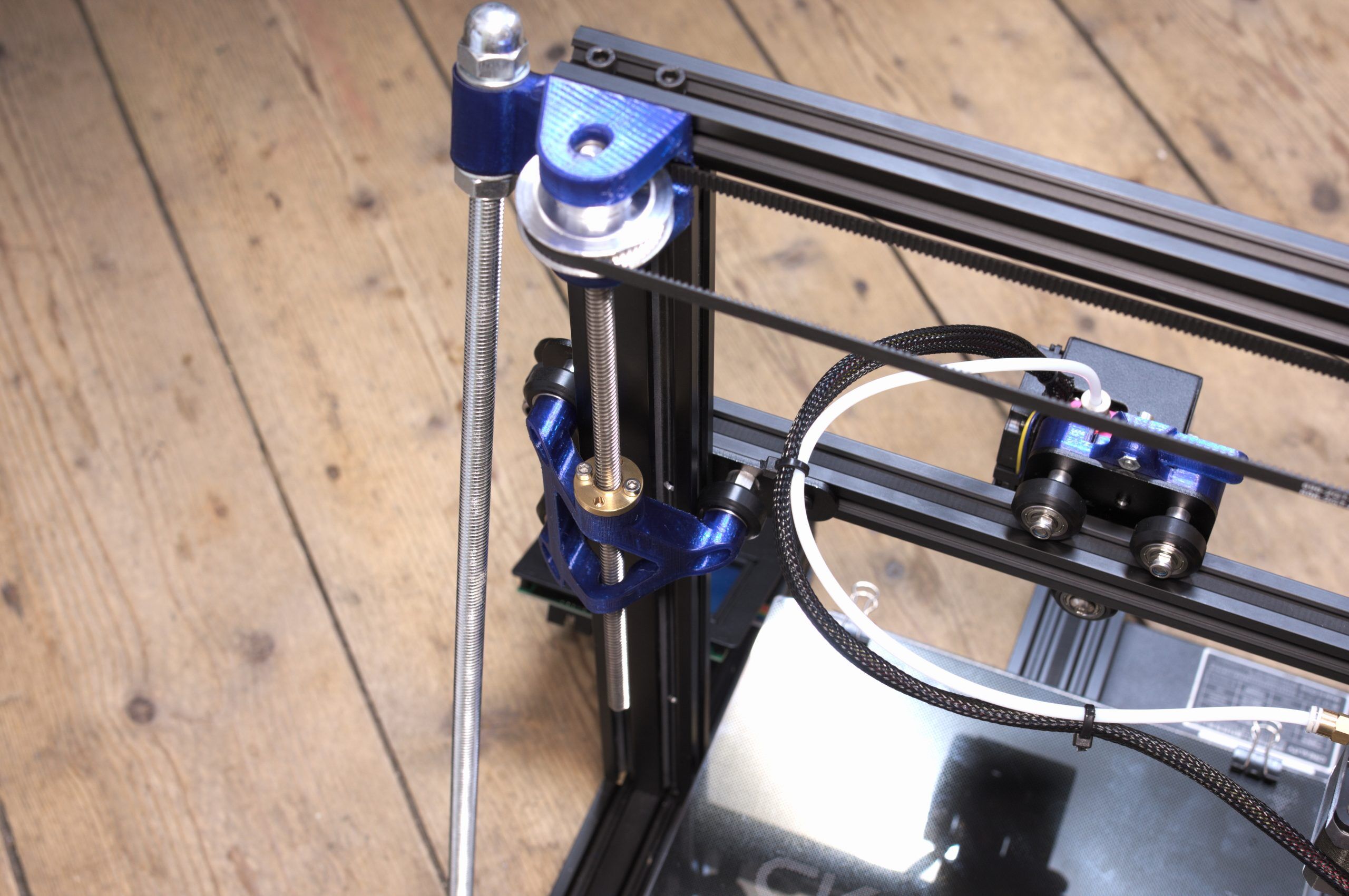
A dual Z axis upgrade with a single stepper is in my opinion a must have for the Ender 3 because this increases the accuracy and reliability of the machine. I have designed one which uses standard parts which don’t need to be modified and it is combined with the frame braces I have designed earlier.
I have added corner pieces without the frame braces if you are just interested in the dual Z axis. I have designed the bracket to be as stiff as possible and therefore it has this odd shape which I am quite happy with.
I have bought all parts from RepRapWorld and it happens to be that the 696 mm closed loop timing belt together with the two 60 teeth pulleys have a center distance similar to the two vertical beams. All holes are slotted so it can be adjusted a bit.
The power supply must be placed somewhere else and I have seen that there are some mods which enable you to do this.
I have made a video about this upgrade in which I show the process.
Print Settings
Printer: Creality CR-10
Rafts: No
Supports: Yes
Resolution: 0.2
Infill: 20%
Filament: PETG
Notes:
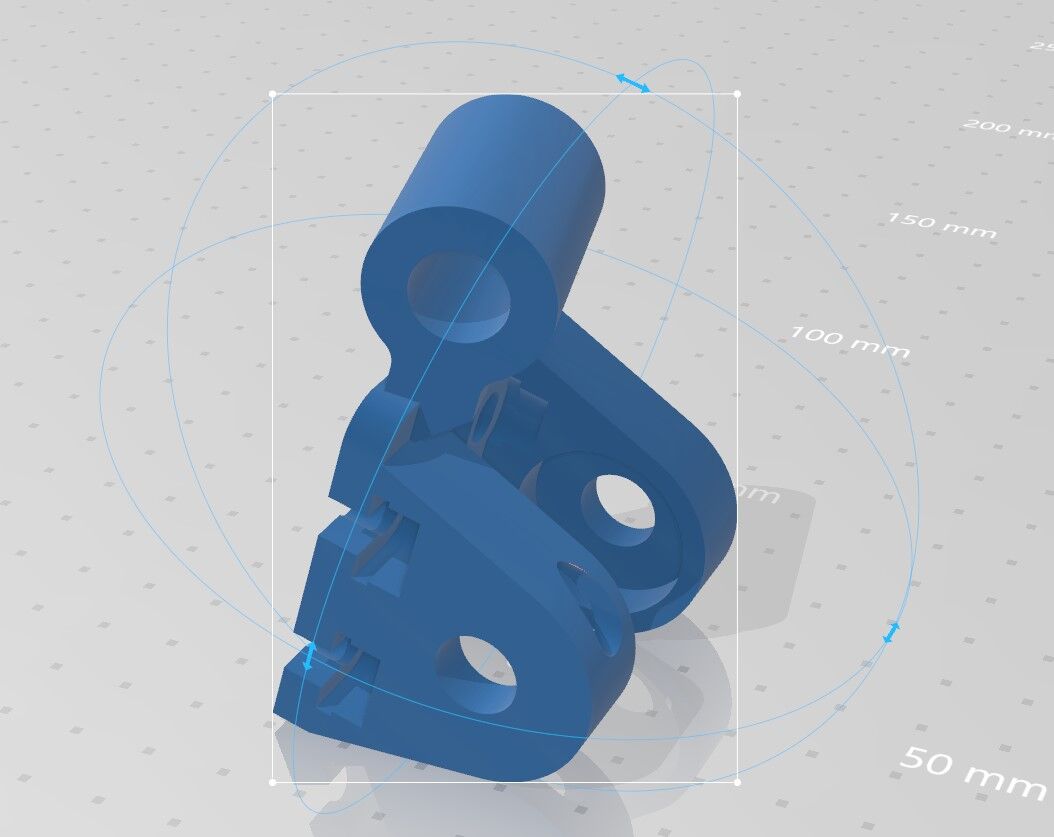
I have added a picture of the orientation of the two upper corners which proved to be successful for me.
Parts needed
- 2× 60 teeth pulley 42mm outer diameter https://reprapworld.com/products/mechanical/pulleys/gt2_pulley_60_teeth_6_mm_belt_8_mm_id/
- 1× 696mm closed loop timing belt https://reprapworld.com/products/mechanical/timing_belts/gt2x6mm_timing_belt_696mm_closed/
- 1x TR8×8 lead screw nut https://reprapworld.com/products/mechanical/linear_motion/tr8x8_leadscrew_nut_8mm/
- 1× TR8×8 300mm lead screw https://reprapworld.com/products/mechanical/linear_motion/lead_screw_tr8x8_8_mm_8_mm_per_rev_30_cm/
- 4× 608ZZ bearing https://reprapworld.com/products/mechanical/bearings/shielded_ball_bearing_608zz/
- 8-14× M5×10 hexagon bolt*
- 8-14× M5 washer*
- 8-14× M5 t-slot nut*
*Amount depends on having the braces or not. More information about the needed parts of the braces can be found here.
I have used the existing screws for mounting the bracket, but I think slightly longer screws work better.
Mounting instructions
- Remove the power supply and Z-axis motor (leave the existing lead screw in)
- Remove both top end caps
- Place the top left corner piece (the one above the Z-motor)
- Press both bearings in
- Press the existing lead screw through the lower bearing and add the pulley together with the timing belt
- Press the lead screw through the pulley, the upper bearing and far enough for the Z-motor and coupler
- Place the Z-motor and mount it to the lead screw
- Fasten the pulley
- Add the top right corner piece and press both bearings in
- Add the bracket with the 300mm lead screw and nut (use a 10mm drill to widen the hole for the lead screw nut if necessary) and do not press the lead screw nut in yet
- Press the 300mm lead screw through the lower bearing and add the second pulley together with the 1mm shim and timing belt
- Press the 300mm lead screw to the right height (just above the upper bearing) don’t fasten the pulley yet
- Press the lead screw nut in the bracket by rotating it downwards and mount it
- Adjust the height of the gantry so that both sides are at the same height. This can be done by rotating the 300mm lead screw and holding the pulley still
- Once the gantry is horizontal you can fasten the second pulley and enjoy printing
If you have any questions or suggestions, don’t hesitate to leave a comment or contact me.
You must be logged in to post a review.


Reviews
There are no reviews yet.